As always reference the LinuxCNC manuals and the LinuxCNC Wiki for more information.
Linear Moves
A linear move is one that goes from the current position to the programmed position in a straight line. LinuxCNC has two basic linear moves G0 and G1. G0 is a rapid linear move that moves at the maximum speed of the machine. G1 is a feed linear move that moves at the speed set by the F word.
G0 X1.200 Z0.100
G1 X1.200 Z0.100 F25
X0
|
Note
|
The following examples use absolute arc distance mode and absolute distance mode unless specificed. |
Circular Feed Moves
A circular feed move uses G2 and G3. The direction is always as viewed from the positive end of the axis that is perpendicular to the active plane… whew that is a mouthful.For a typical lathe the imaginary Y axis positive end is below the lathe so you have to lay on the floor and look up… or just remember that G2 is CCW and G3 is CW as viewed from the top of the lathe.
Center Format Arcs
Center format arcs are more accurate than radius format arcs and are the preferred format to use. Center format arcs start from the current position and need the end point and the offset from the current position to the center of the arc.
Programming an Arc
-
The active plane needs to be G18 the XZ plane.
-
The Current position is the start of the arc.
-
The End Position is the end of the arc.
-
The Offsets are I for X offset and K for Z offset.
The start point and end point are fairly easy to come up with, what trips most people up is the offsets. Starting with the X offset if the center of the circle is on the positive side of the start position then the I offset is a positive number. If the center of the circle is on the negative side of the start position then the I offset is a negative number.
The easiest way to calculate the arc is with a cad program like Qcad. Lets create a simple arc that has the following characteristics.
-
Start position is X0.2000 Z0.0000
-
End position is X0.3000 Z-0.1000
-
Arc center is at X0.2000 Z-0.1000
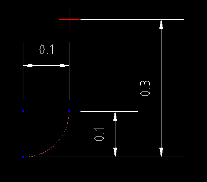
If you draw this out in Qcad you can see that the arc center is same as X start and 0.1000 in the Z minus direction from the start point. The following image shows the CAD drawing used in this example. The arc center is the red circle with the blue dot in it and the arc is the red dotted line. The red cross is the X0 and Z0 point.
First we have to move to the start position so if your following along with the Axis lathe simulator in the MDI window issue the following G code:
G0 X0.200 Z0.100
G1 Z0.000 F2 (feed move into the part)
Now lets work out the arc… the end postion is X0.300 Z-0.100 so the first part if the G code is:
G3 X0.300 Z-0.100
The offset from the start position is the same as the X location so I0.0000 is the X offset. The center of the arc is 0.1000 from the start postion in the Z axis so the Z offset is K-0.100. Our completed code looks like this:
G3 X0.300 Z-0.100 I0.000 K-0.100
Lead in and lead out are usually important on a lathe depending on the part. The full code including a lead in and a lead out is shown in the following code.
G8 G20 G18 G40 G64 P0.001 G80 (preamble)
G0 X0.200 Z0.100
G1 Z0.000 F2
G3 X0.300 Z-0.100 I0.000 K-0.100
G1 X0.400
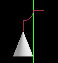
This made the CW direction arc as shown in the following image.
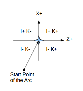
The following chart shows the sign of the offset for an arc in the G18 (XZ) plane. The view is as seen from the top of the mill looking down through the Z axis. The axis directions are the same way the tool will move when you press the plus and minus direction keys for that axis. Looking at the diagram the center mark is the start of the arc and the quadrant the center falls into shows the sign for the offsets.