As always reference the LinuxCNC manuals and the LinuxCNC Wiki for more information.
Basic Ladder Concepts
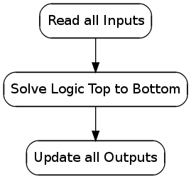
Ladder Scan
The ladder scan is different than programming languages in the way it functions. The first part of the scan is to read the state of all the inputs. The next part of the scan is to solve the logic for each rung to determine if the rung evaluates to true or false. The rungs are solved from top to bottom. The last part of the scan it updates the outputs of each rung based on the true/false condition of the rung.
Coding Ladder
Some important things to remember when coding in ladder.
-
Never have the same output more than once.
-
What happens after the logic is updated the last output state will be the state that is written to the output. If the first occurrence of the output is on and the second occurrence is off the output will always be off.
-
-
Avoid using Latch and Unlatch, instead use a seal-in circuit.
-
Never code an input condition based on the output condition on the same line.
Example Circuits
In the following circuits the addressing used is:
-
Physical Inputs are I/n
-
Physical Outputs are O/n
-
Internal Bits are B/n
The symbols used for I/O is:
-
Normally open contact [ ]
-
Normally closed contact [/]
-
Rising edge contact [^]
-
Normally open Output ( )
-
Normally closed output (/)
Inputs and outputs are what the real world devices are connected to.
A contact can be any valid bit like input, output, or internal bit.
An output can be an internal bit or a physical output.
A rising edge contact will be on for only one scan.
    I/0               O/0
----[ ]---------------( )
In the above simple circuit when the input I/0 is on the output O/0 will be on.
    I/0       I/1      O/0
----[ ]-------[/]------( )
           |
    O/0    |
----[ ]----|
In the above seal-in circuit when the input I/0 is on and I/1 is off the output O/0 is turned on. When this happens the contact O/0 comes on and latches the circuit on even if I/0 is turned off. So if I/0 was a start push button and I/1 was a stop button when you press start the output comes on and stays on until you press the stop button which breaks the circuit to output O/0. When the output O/0 goes off so does the contact O/0. This circuit also demonstrates the basic branch circuit with the second line being an input branch.
Step 1
    I/0       B/1      B/0
----[ ]-------[/]------( )
           |
    B/0    |
----[ ]----|

    B/0                O/0
----[ ]----------------( )

    I/1      B/0       B/1
----[ ]------[ ]-------( )

Step 2
    B/1      B/3       B/2
----[^]------[/]-------( )
          |
    B/2   |
----[ ]---|
In the Do/Done circuit the first rung initiates an action by turning on an internal bit and sealing itself in when input I/0 comes on. The second rung turns on the output when B/0 is on. When the action is done the input I/1 comes on and if we are still in step 1 the input turns on the done bit B/1 which breaks the seal-in of the first rung and initiates the second step.
One key is that step 2 can not be initiated unless you are in step 1 and step 1 is complete. Step 2 will be just like step 1 and when complete it could initiate step 3. For a repeating loop have the last step initiate the first step.