As always reference the LinuxCNC manuals and the LinuxCNC Wiki for more information.
The Latching Circuit
The basic latching circuit has a momentary input that turns on the output. The output latches in the circuit until another contact breaks the circuit.
This is one of the basic circuits in ladder logic.
-
Do Something until some condition tells us to stop.
In the following circuit we have Input 1 (%I1) as the trigger. Input 2 (%I2) is the release. The internal bit %B0 is the output and the latch.
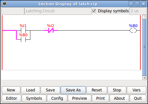
In the following circuit we can see %I1 is closed and the purple line that represents flow is complete to %B0.
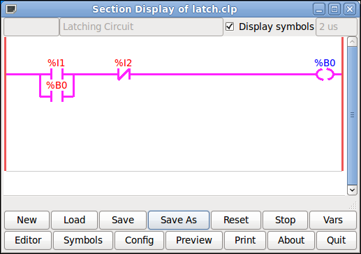
In the following circuit we can see %I1 has been opened and the circuit is being held in by the %B0 contact.
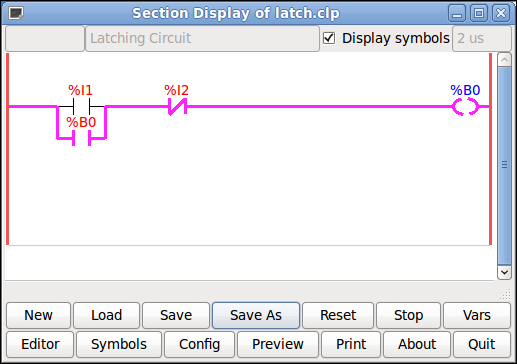
In the following circuit %I2 is on and because the contact is a normally closed (N/C) the circuit is broken and the latch is released.
